Anuj Gajjar

My LinkedIn Profile
My Github Profile
Email: anujygajjar1@gmail.com
Phone: 857-225-4456
Embedded Design Final Project: Wiimote Control of Robotic Arm
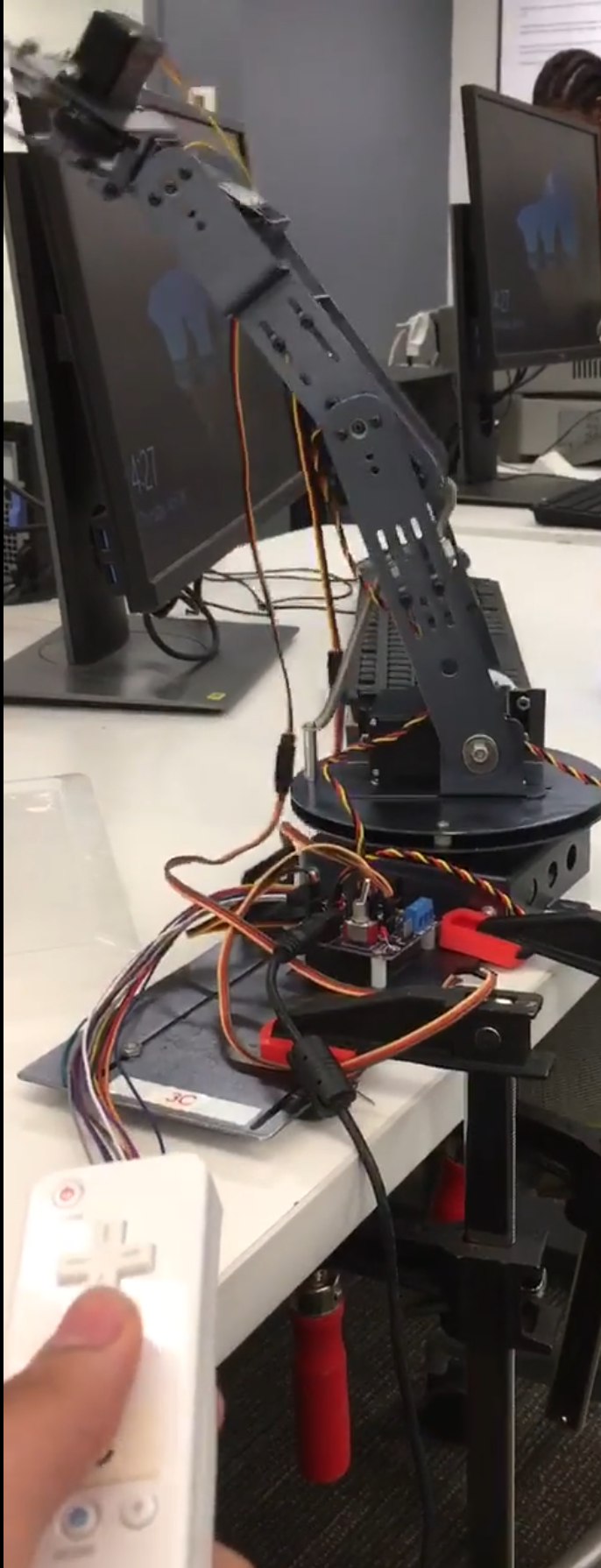
Caption: A Wiimote controlling the robotic arm.
Goal: To control a robotic arm (consisting of servos) via a Wiimote through a ZedBoard, an embedded device.
Context: This project was the final project for my introductory Embedded Design class. This project is meant to demonstrate my understanding of C++ programming, logic design, FPGA programming, and the use of a ZedBoard with an ARM processor running Linux OS.
Summary: I was able to utilize C++ programming, and logic design with FPGA programming (on Simulink) to succesfully control a robotic arm (through PWM) via a Wiimote. The C++ programming was used to process and read Wiimote acceleration and button events, with the servos being controlled through Simulink programming.
The code for this portion of this project is on my github.
Credit goes to the Embedded Design teaching faculty of the Fall 2019 semester at Northeastern University.
The Logic Design
In this project, we used logic design to control the robotic arm using PWM signals via the GPIO of the ZedBoard. The purpose of this logic was the following:
- Give accessible inputs for C++ programming (this is already allowed by the prog)
- Allow C++ programming to control the motors
- Control the motors servo angle
- Control the motors speed
- Integrate motor angle and speed control
Note that the robotic arm consisted of five servos on a: base, arm, joint, wrist, and gripper.
This logic was designed through MATLAB’s Simulink.
The first step was to design the logic circuit for the angle to PWM conversion. This logic circuit would translate a given angle (i.e 45 degrees) and set it to the correct corresponding period for a PWM signal. Earlier in the semester, as an assignment, I figured out the correct calculation to converting the angle to the PWM signal. The PWM period = 50us * Angle + 3000us (this is the period in which the PWM signal is “on” or 1) over a total PWM period of 20000us.
The following image shows the circuit design I made for PWM angle control:
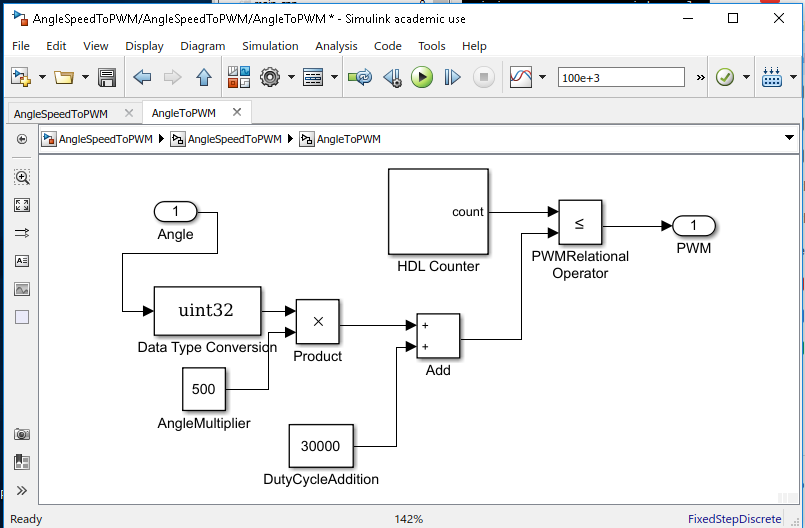
Caption: The logic circuit design for servo angle control.
This logic design involved multiplying the angle by 500 (10^-5 seconds), then adding 30000 (10^-5 seconds) to that product. This was then placed in a relational operator which compared the duty cycle time to a counter that runs through one period of the cycle.
The following images shows simulations of the circuits behavior, I tested the circuit for angles of 0 degrees, 90 degrees, and 180 degrees.
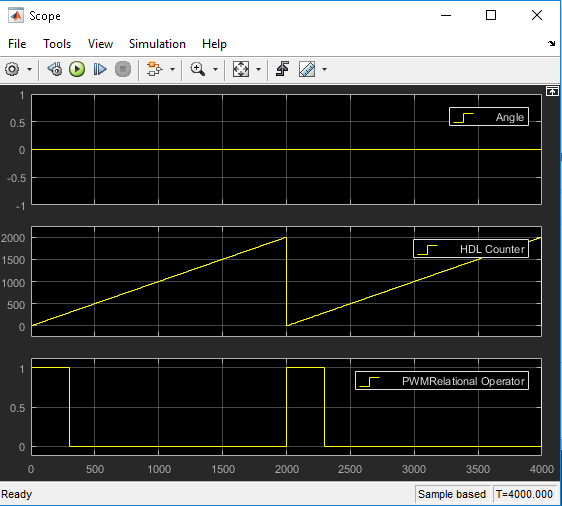
Caption: The simulation for a 0 degrees PWM pulse, an “on” period of 300*10^-5 seconds is expected.
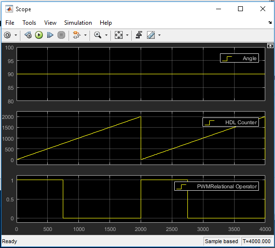
Caption: The simulation for a 90 degrees PWM pulse, an “on” period of 750*10^-5 seconds is expected.
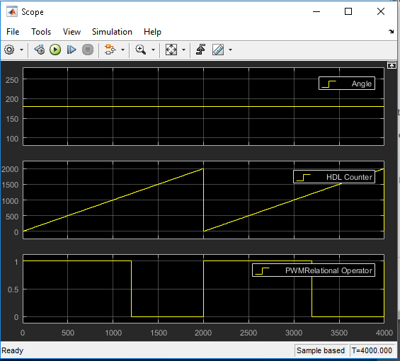
Caption: The simulation for a 180 degrees PWM pulse, an “on” period of 1200*10^-5 seconds is expected.
Since the simulations correctly verified the design, the next step was to design the circuit for speed control.
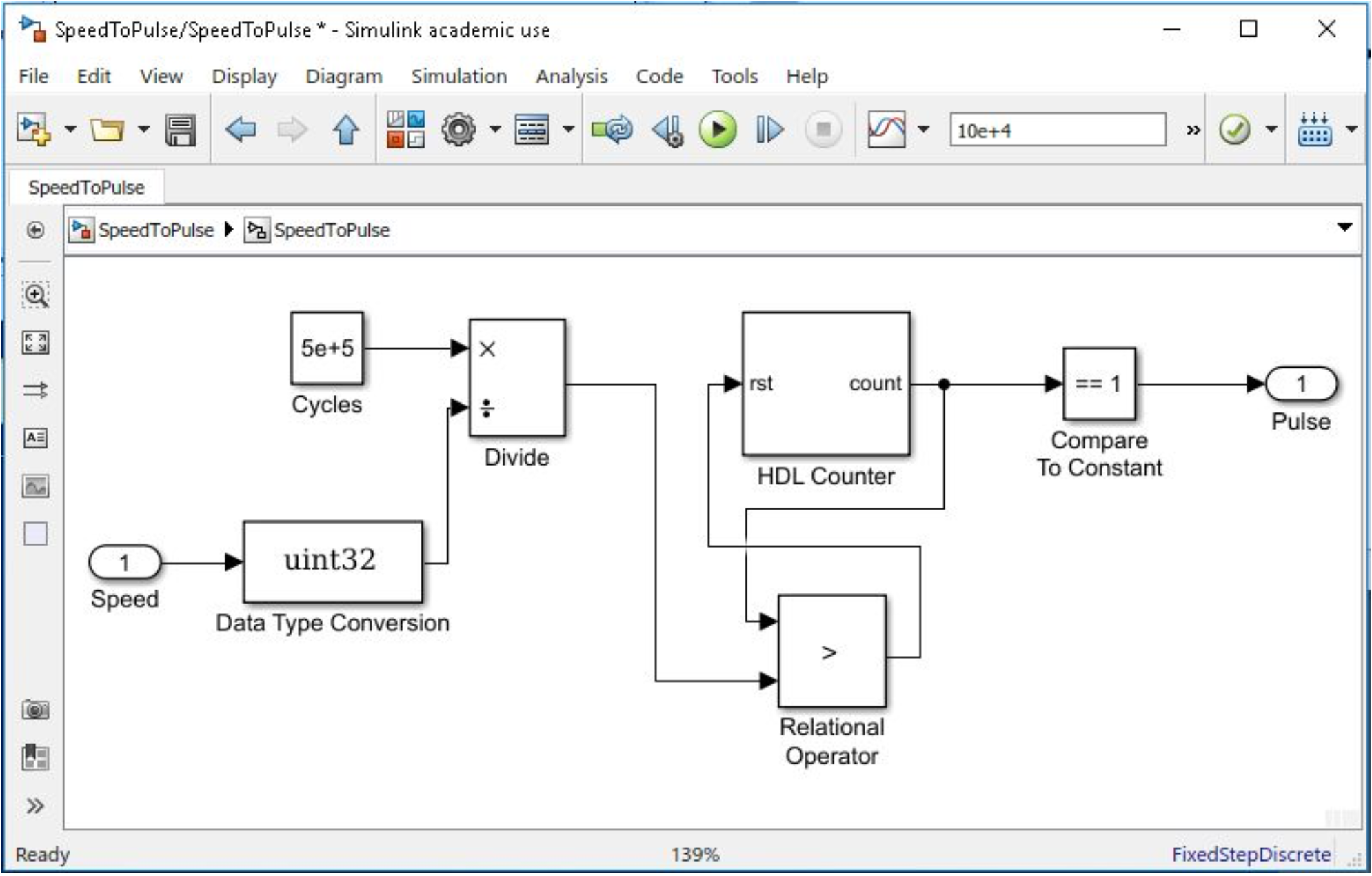
Caption: The logic circuit design for servo speed control.
This design firstly involved dividing the number of clock cycles in one second of the ZedBoard by the speed, and then using a relational operator to compare the value to a counter that runs increments by one from zero to the number of PWM cycles in one second. When this relational operator is true, the counter is reset, and since the counter resets to a value of 1, it is compared to a constant of 1. When this compare to constant is true, a on value is generated in the pulse. This switching of 1 and 0 in this outputted pulse allows the setting of the speed for a PWM pulse.
This design was also simulated for verification, which was simulated for 10 degrees per second, and 100 degrees per second.
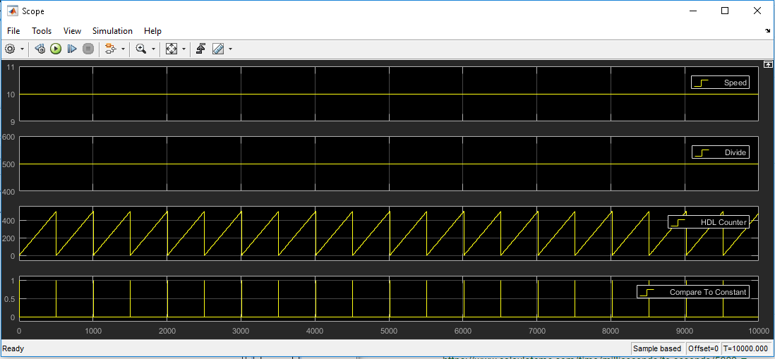
Caption: The simulation for 10 degrees per second speed control.
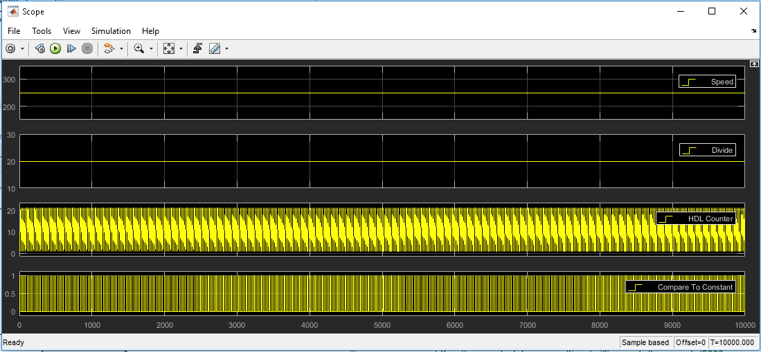
Caption: The simulation for 100 degrees per second speed control.
The next step was to integrate the speed and angle control circuits. The following circuit was designed:
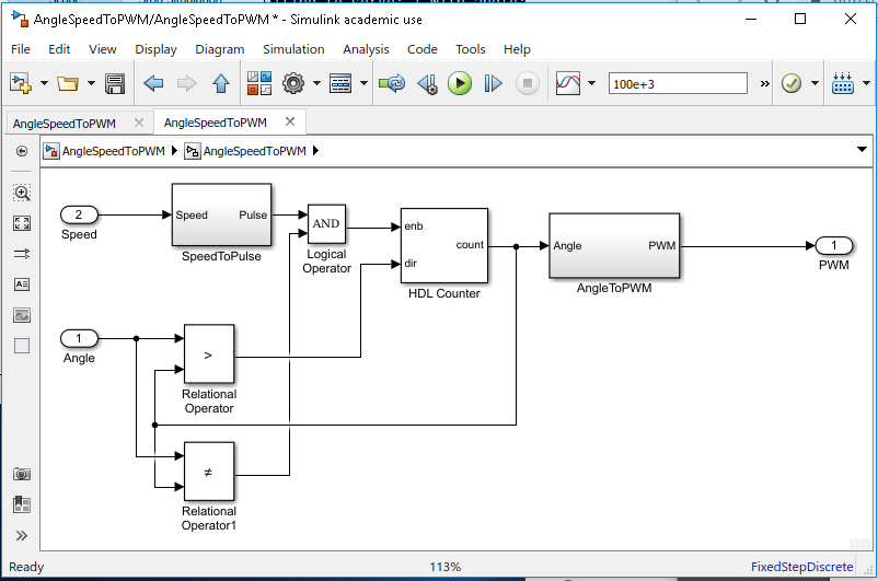
Caption: The integrated logic design to conduct angle and speed control of a servo.
This design simply just involves having the circuit that generates a pulse from the speed of the servo to enable and disable a counter that increments or decrements the angle by 1 from 90 degrees (this angle is stored in a counter). This counter output is then ran through the PWM pulse generator circuit. After that step, the desired PWM signal is outputted.
Again, this circuit was simulated.
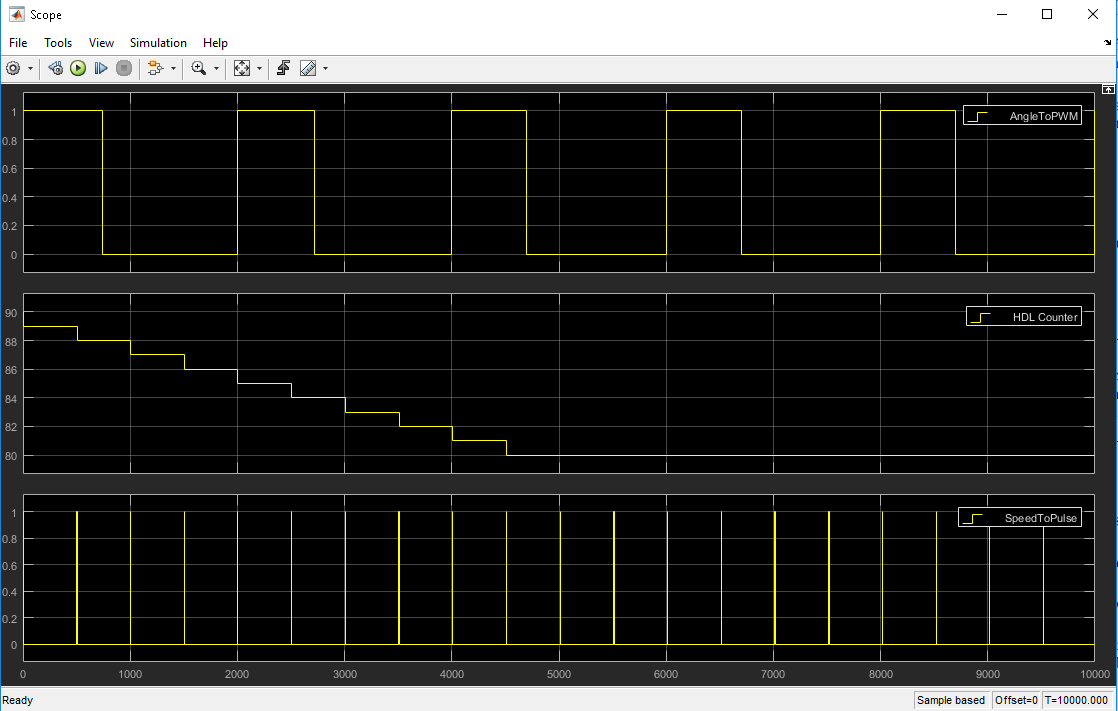
Caption: The simulation for the speed and angle control circuit, with a change in angle from 90 to 80 degrees at a speed of 2 degrees/s.
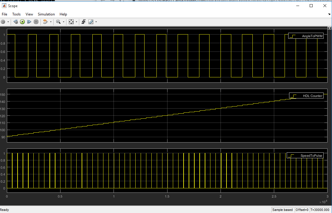
Caption: The simulation for the speed and angle control circuit, with a change in angle from 90 to 80 degrees at a speed of 2 degrees/s.
In the first simulation which runs for 10 seconds, in which the desired servo angle is 80 degrees, the servo speed is 2 degrees/s, it appears that the correct PWM value for 80 degrees is achieved after 5 seconds; thus the correct angle and speed was achieved.
In the second simulation, in which the desired servo angle is 150 degrees, and the servo speed is 20 m/s. It appears that the correct PWM value for 150 degrees is achieved after 3 seconds; thus the correct angle and speed was achieved.
Given these simulations, the logic design I made for PWM servo control appears to be properly functional.
The final step logic-wise was creating the circuit for all 5 servos on the robotic arm, and properly mapping the memory registers of I/O ports (so that the C++ programming can utilize these input and output registers).
This image shows the final logic circuit design:
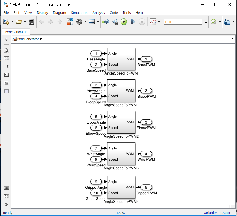
Caption: The final logic design for all servos.
With the following memory mapping:
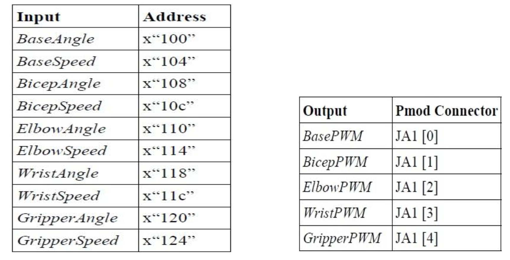
Caption: The memory mapping for the input and output ports.
This logic was then programmed into the FPGA of the ZedBoard.
The next was step was to utilize C++ programming to allow the Wiimote to control robotic arm servos.
The C++ Programming
The first step was to create a connection link between the Wiimote and a Bluetooth receiver connected to the ZedBoard. This was done through a shell script that initialized the connection, and setup the memory location to read Wiimote acceleration events. The goal was to use the Wiimote acceleration (or movement) to control the base servo, while the Wiimote buttons are used to control the four other servos.
Then the C++ structure was setup to read and process the Wiimote button and acceleration events and send the desired values to the inputs of the programmed logic, thus allowing control of the robotic arm from the Wiimote. This was the following structure generated:
- main.cpp
- WiimoteBtns.cpp: Reads and processes wiimote events and sets the desired speed and angle values
- RoboticArm.cpp: Controls the inputs sent to the registers that hold the inputs to the logic design that controls the servos
The Result
The following video shows the final result:
Caption: The video demonstrating the operation and control of the robotic arm. The x-axis acceleration of the Wiimote controlled the base servo, while the button presses on the Wiimote control all other servos.