Anuj Gajjar

My LinkedIn Profile
My Github Profile
Email: anujygajjar1@gmail.com
Phone: 857-225-4456
Generate Product Development: Smarty Pill
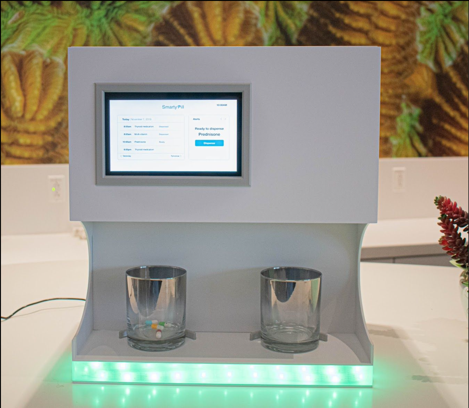
Caption: An example final implementation of the automatic pill dispenser.
Goal: Develop a prototype of an automatic and adaptive pill dispensing mechanism.
Back Story: Our client came to Generate Product Development with the idea to design a prototype of an automated pill dispenser. Our client had previously developed versions of automated pill dispensers, however he encountered challenges with not being able to dispense pills of various sizes and shapes, and he wanted a more comprehensive system. Our deliverables for this product was to develop a pill dispensing mechanism that can adapt to all shapes and sizes of pills, develop a frontend that allows user and caretaker registration, develop a backend (that holds user and caretaker data), develop a communication protocol between the backend server and a user device, prototype the user interface (UI) on a user device, develop a comprehensive firmware system, and develop a PCB for power management. Due to these deliverables, we were split into two teams, a hardware and software team. The hardware team was tasked with developing the mechanism, firmware, and power management, while the software team was tasked with developing the front end and back end, and the communication protocol. My role on the project involved prototyping the UI, developing the firmware, and creating the power management PCB.
Summary: Overall, we were successfully able to develop a functional prototype of all of the systems of the automated pill dispenser, however we were not able to integrate every system together. Our software team developed a frontend and backend system and a communication protocol between the backend system and a user device, the mechanical team (part of hardware team) was able to develop an adaptable pill dispensing mechanism (not shown here as the system is proprietary), and the computer and electrical engineering team (also part of hardware team) was able to develop the power management PCB and the comprehensive firmware system, we were also successfully able to prototype the user interface. Despite our lack of integration, our client was happy with what we developed.
Credit goes to the Fall 2019 Smarty Pill Team of Generate Product Development.
Power Management PCB
The automated pill dispenser we were designing included a Raspberry Pi (for systems control), with stackable motor hats (for motor control of servos and steppers on the system), a touchscreen display, an LED and speaker (for feedback), a sensor system (for sensing the dispensing of pills), and an analog-digital converter (ADC). Due to the presence of all these systems, it was necessary that we build a PCB for centralized power management and cable organization.
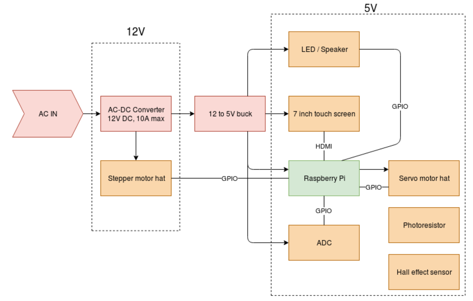
Caption: Block diagram of the system.
Due to the presence of all these systems we built a PCB with the following considerations:
- Allow easy access to GPIO pins on the Raspberry Pi
- 12V and 5V power rails
- Access to the above power rails
- Access to an on-chip ADC
- Decoupling
- Charging/switching circuitry for backup battery
Note that we decided to buy external electronic equipment for converting AC voltage to DC voltages.
With these considerations we came up with the following circuit design:
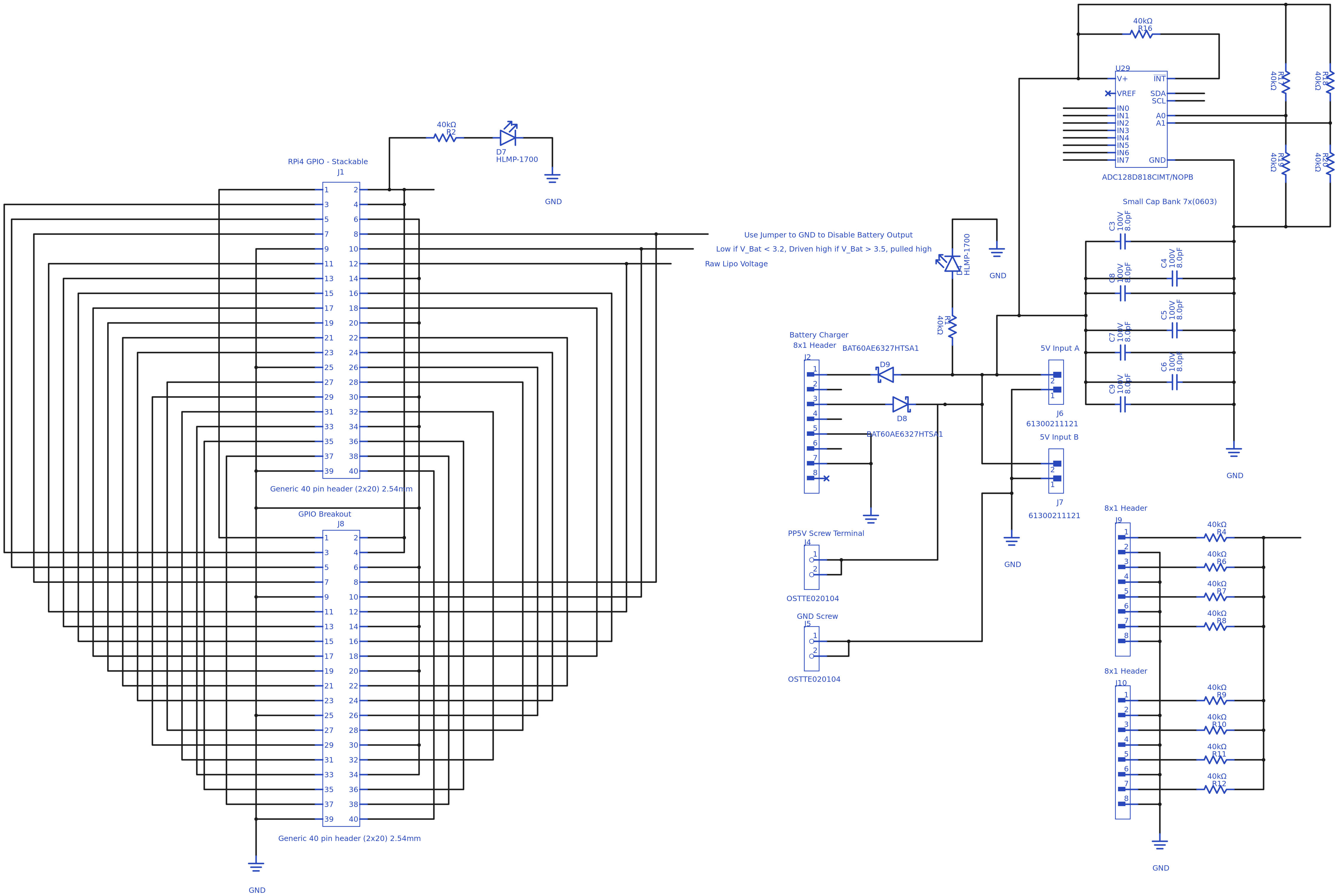
Caption: Schematic of the Power Management PCB we designed.
With this schematic we then generated the following design and routing for the PCB:
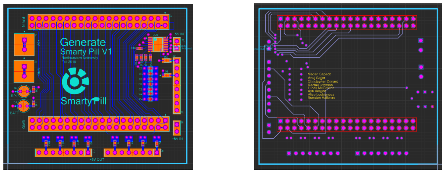
Caption: The routing of the power management PCB.
While we were able to design the PCB, due to time constraints with the PCB fabrication, we were not able to fully implement the PCB. However, we were able to protoboard the system. The following video shows the electrical systems functioning.
Caption: A video showing the functionality of the power management design.
After the project came to an end, the PCBs were fabricated.
Caption: The fabricated PCB.
Credit goes to the computer and electrical engineers on the Fall 2019 SmartyPill team.
Firmware Library
As mentioned above, due to the presence of several systems, we wanted to centralize the control of these systems in a Raspberry Pi; thus requiring us to develop a comprehensive firmware library that covered all of the system we developed and allowed the firmware for other systems to be easily added to the overall firmware library. Part of the firmware involved the communication channel between the user device on the Raspberry Pi and the backend server. We took an object-oriented approach in designing the firmware.
Before writing any code we defined the following structure for the firmware:
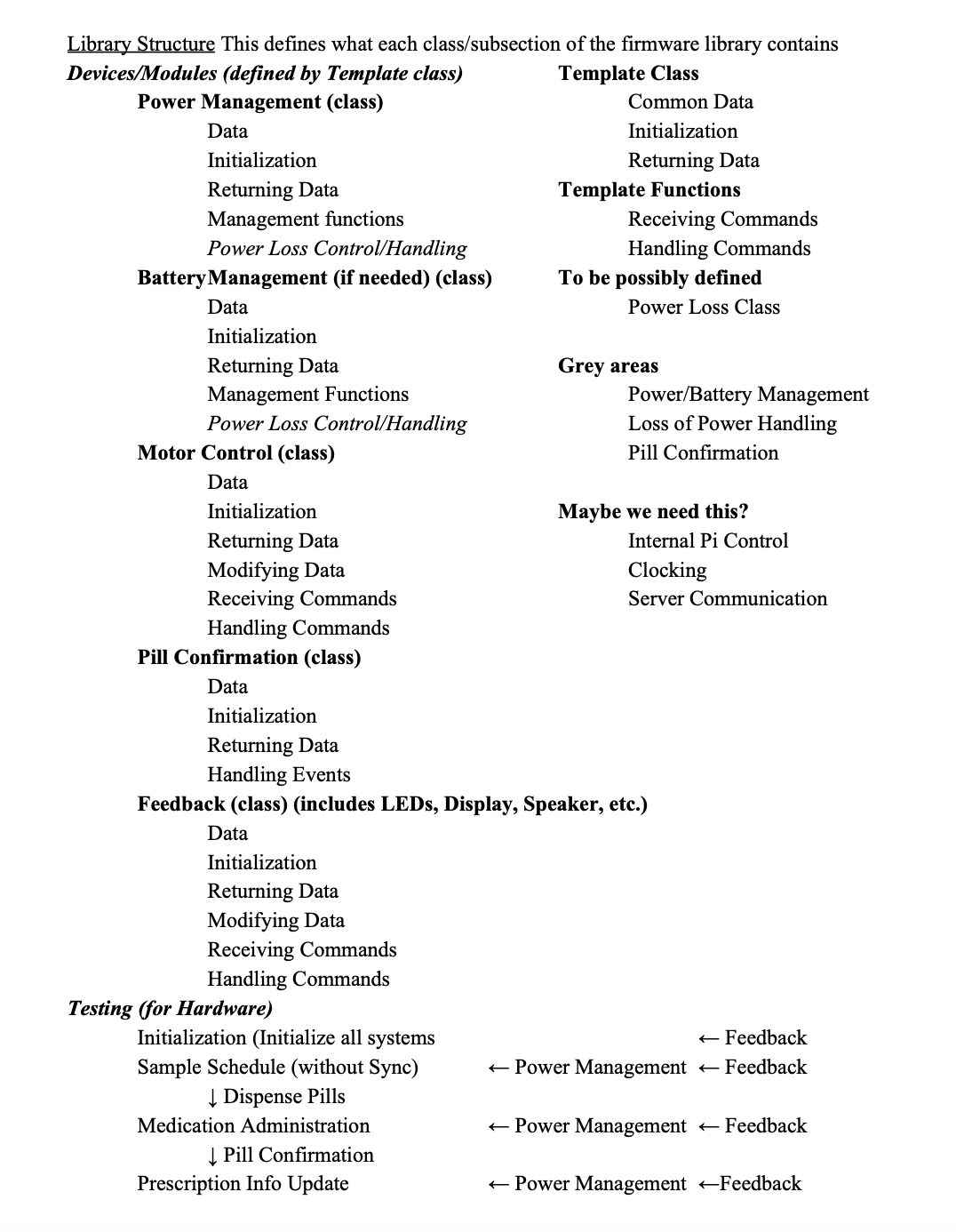
Caption: The initial firmware structure we defined for the firmware.
Due to the ease of use we decided to write the firmware in Python. Thus the following structure we defined earlier ended up looking this in Python:
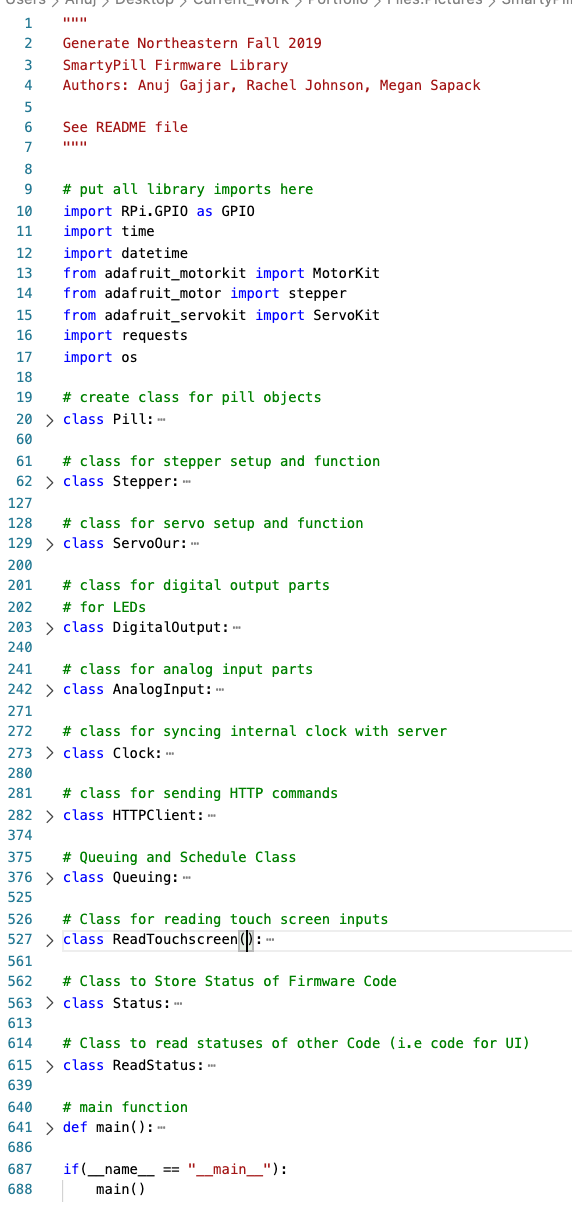
Caption: The structure of the firmware in Python.
The following image shows an example of a class we implemented in Python:
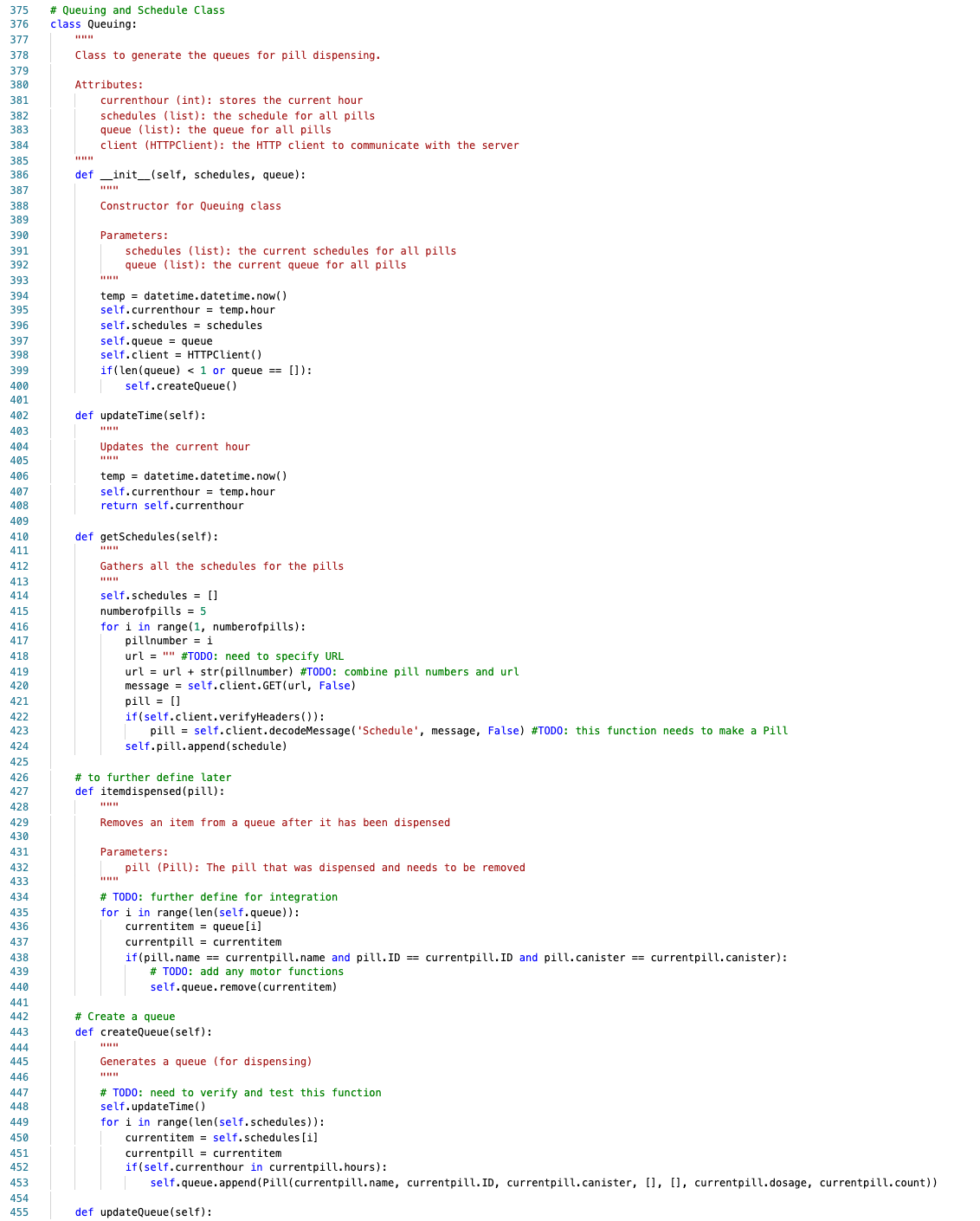
Caption: An example of a class we implemented.
Once we finalized the firmware library, documentation was of paramount importance, the following image shows the README file we defined for the firmware library.
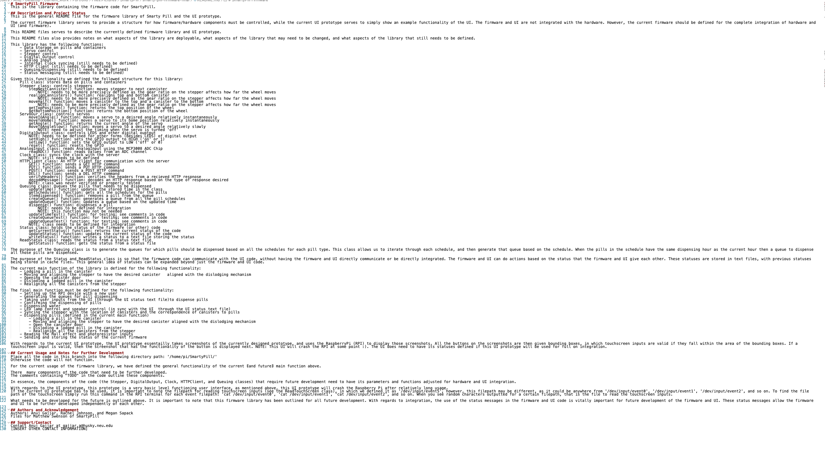
Caption: The README file we wrote for the firmware library.
Credit goes to the computer and electrical engineers on the Fall 2019 SmartyPill team.
Reflections
The SmartyPill project that we took on at Generate Product Development was an ambitious project. We had to develop a detailed project completely from scratch, and we ended up running into time constraint issues as the project approached an end. Nonetheless, we were successfully able to develop an adaptable pill dispensing system, frontend and backend components, a communication protocol between the backend and user device, prototype the user interface, develop a firmware system, and develop a power management PCB. Our main challenge was that we either not able to fully fabricate a component or integrate all the components together.
All in all, we were able to prototype each system individually.
Overall, my experience on the SmartyPill project further introduced me to what it is like to work on a large project that involves at least a couple teams. I was introduced to more industry-facing concepts of computer and electrical engineering. My work on the power management PCB and firmware system further introduced me to firmware and embedded system development and circuit and PCB design.
Again, all credit goes to the Fall 2019 SmartyPill Team.